Douglas L. Sondak
Boston University
Daniel J. Dorney
Virginia Commonwealth University
(presently NASA Marshall Space Flight Center)
Accurate unsteady temperature distributions within jet engine turbine blades are difficult to predict, so large safety margins must be employed to ensure that hot spots and thermal cycling do not damage the blades. Improved temperature predictions could lead toward higher thermal efficiencies and longer blade life.
It is common practice to assume that surfaces are adiabatic when computing blade temperatures, but in reality there is substantial heat transfer between the blades and the working fluid. In order to accurately simulate blade surface temperature, it is therefore necessary to couple unsteady flow and conduction heat transfer solvers.
In the present study, an unsteady, 3-D, finite-difference heat conduction solver has been developed to compute the temperature field within a turbine blade. It has been coupled with an unsteady, 3-D, compressible, turbulent, finite-difference Navier-Stokes solver. The flow and heat transfer in a single-stage turbine with a non-uniform inlet temperature distribution (hot streak) typical of that in an actual jet engine was then computed, and the unsteady temperature field within a rotor blade was examined in detail.
In the flow solver, the Navier-Stokes equations were solved using an implicit, time-marching, finite- difference scheme. The procedure is second-order accurate in time and third-order accurate in space. The equations were solved using approximate factorization and a block tridiagonal solver. The unsteady heat equation was solved using a similar technique.
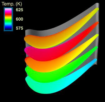
Contours of rotor temperature are shown at an instant in time at 10%, 30%, 50%, 70%, and 90% span. This figure shows that the hot streak has migrated toward the tip of the rotor, since the hottest section is at 70% span, and the hot streak was introduced at 40% span.
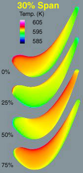
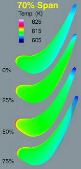
Rotor temperature variation is shown at 0%, 25%, 50% and 75% of a periodic cycle at 30% and 70% span. Strong temperature variation is shown as the hot streak interacts with the blade.
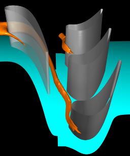
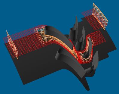
A circular hot streak with a hyperbolic tangent profile is introduced at the inlet boundary at 40% span. An instantaneous temperature iso-surface shows the interaction between the hot streak and the vane and rotor blades. A rotor blade has been copied in the circumferential direction to illustrate periodicity.
The actual domain in the simulation contained one vane and two rotor blades. In this figure (at top), the domain has been duplicated in the circumferential (periodic) direction for clarity. Each passage is modeled with an overset H-grid (red) and O-grid (peach). Flow is from left to right. The rotor blades (downstream blade row) move with respect to the vanes, and the flowpath is stationary downstream of the rotor. When the rotor blades complete each traversal of the vane, they ratchet back to the top of the domain in the circumferential direction.
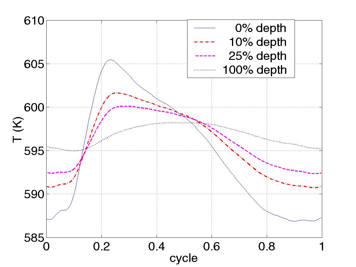
Unsteady temperature traces are shown at the rotor leading edge, 30% span, at various depths along the mean camberline. 100% depth is defined as a distance of 0.05 chord.
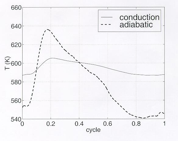
Results for the coupled model are compared with those from a simulation with the commonly-used adiabatic blade surface boundary condition. Heat transfer in the blade has a strong damping effect on the unsteady temperatures.
Published as AIAA paper 99-2521, also AIAA Journal of Propulsion and Power, Vol.16, No.6
Hardware: SGI Origin 2000.
Software: MPI.
Graphics programming: Erik Brisson and Kathleen Curry, Scientific Computing and Visualization Group, Boston University.