Douglas L. Sondak – Boston University
Daniel J. Dorney – NASA Marshall Space Flight Center
Introduction
Turbomachines for propulsion applications operate with many different working fluids and flow conditions. The flow may be incompressible, such as in the liquid hydrogen pump in a rocket engine, or may be a supersonic gas, such as in the turbine which drives the hydrogen pump. Unsteady compressible fluid flow is described by a mixed set of hyperbolic-parabolic partial differential equations, while unsteady incompressible flows are described by a mixed set of elliptic-parabolic partial differential equations. Since the nature of the equations is different, separate codes with different numerical methods have traditionally been used for incompressible and compressible flow solvers.
The General Equation Set (GES) method [1] can be used to solve both incompressible and compressible flows, and it is not restricted to perfect gases, as are many flow solvers. Since the GES method was developed based on a preconditioning method, preconditioning can be used to accelerate the solution, with dual time step used to maintain time accuracy. With appropriate choice of preconditioning parameters, the method reduces to the pseudocompressibility method, which is commonly used to solve unsteady, incompressible flows.
An unsteady turbomachinery flow solver has been written using the GES method [2]. The code can handle a variety of fluids in liquid and gaseous phases, including water, hydrogen, oxygen, nitrogen, RP1 (kerosene), and perfect gases.
The code is based on Corsair, a well-established perfect-gas turbomachinery flow solver. Corsair has been under development for 17 years, and is used by more than 25 industrial, academic, and government organizations. It was awarded the 2005 NASA Marshall Space Flight Center “Software of the Year” award.
Results
The code has been applied to a variety of turbomachinery configurations. Four examples of rocket-engine turbomachinery components with different working fluids are shown here: 1) turbopump inducer, 2) 2-D turbine, 3) 3-D turbine, 4) centrifugal impeller test rig with vaned diffuser. All of these were unsteady simulations, and the results are shown at arbitrary snapshots in time.
Inducer
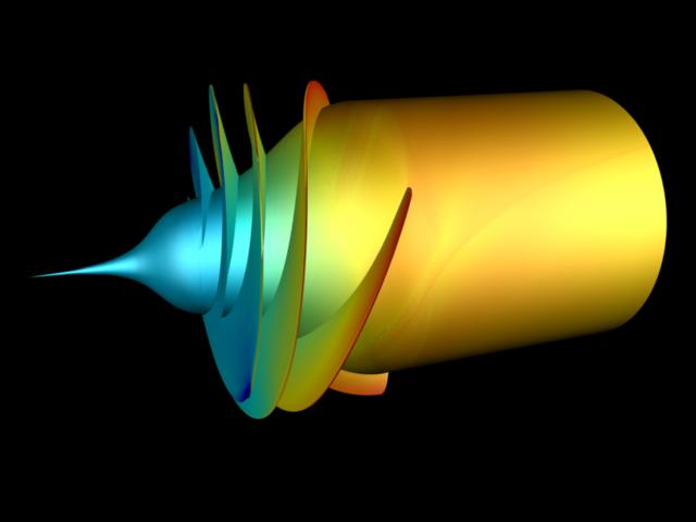
Turbopumps are used to feed the fuel and oxidizer to liquid-fueled rocket engines. If the inlet pressure to the pump is too low, cavitation can occur, which is a condition in which vapor bubbles form, degrading pump performance. In order to increase the pump inlet pressure, an “inducer” if often used, which can be thought of as a “booster pump.”
A simulation was performed to examine the flow field in a liquid hydrogen inducer. The 4-bladed geometry is typical of those found in fuel and oxidizer turbopumps for rocket engine applications. Figure 1 shows the inducer blades colored by surface pressure. The pressure is normalized by the minimum and maximum values throughout the flow field.

2-D Turbine
Turbopumps in rocket engines are usually driven by turbines. The unsteady flow field through a 2-D turbine geometry typical of those used to drive low-pressure fuel or oxidizer turbopumps has been simulated using the GES code. In this case the working fluid was liquid oxygen. The domain consisted of two vanes and three rotor blades. A plot of nondimensional pressure through the passages is shown in Figure 2.
3-D Turbine
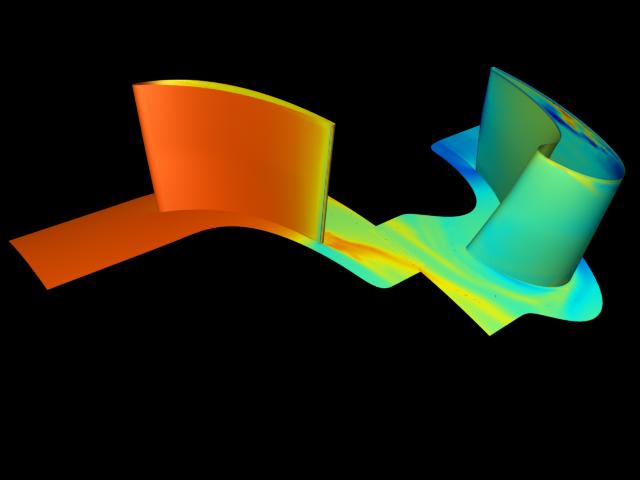
To demonstrate the ability of the code to operate on compressible flows, a 3-D, unsteady flow simulation was performed with gaseous hydrogen as the working fluid. Again, this turbine geometry was typical of those used to drive low-pressure fuel or oxidizer turbopumps. The domain consisted of a single vane and a single rotor blade. Nondimensional surface pressure contours are shown in Figure 3.
Centrifugal Impeller/Diffuser
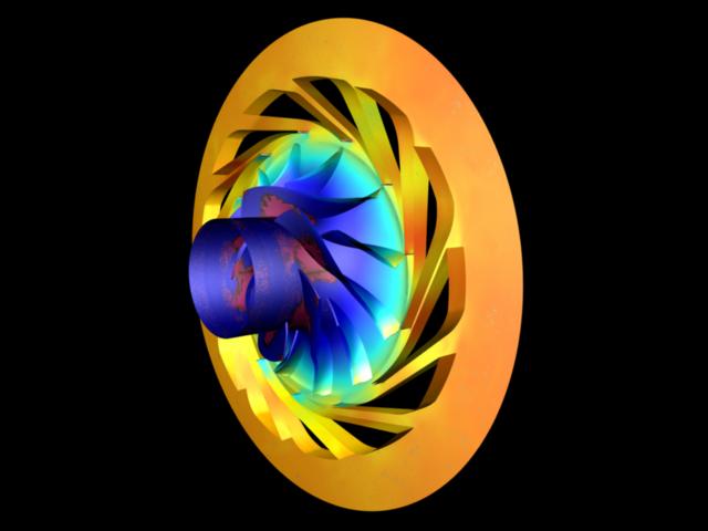
The final example is that of a centrifugal impeller with a vaned diffuser. The impeller contained 12 main blades and 12 splitter blades, and the diffuser contained 13 vanes. The geometry is based on an experimental test rig which used water as the working fluid, so the simulation was also performed using water. Resulting instantaneous, nondimensional surface pressure contours are shown in Figure 4.
References
[1] Venkateswaran, S., and Merkle, C. L., “Analysis of Preconditioning Methods for the Euler and Navier-Stokes Equations,” Von Karman Institute Lecture Series, March 8-12, 1999.
[2] Sondak, D. L., and Dorney, D. J., “General Equation Set Method for Compressible and Incompressible Turbomachinery Flows,” AIAA paper 2003-4420, 39th AIAA/ASME/SAE/ASEE Joint Propulsion Conference and Exhibit, Huntsville, AL, July 20-23, 2003.