
Mechanics of Materials: Bending – Shear Stress
Transverse Shear in Bending
As we learned while creating shear and moment diagrams, there is a shear force and a bending moment acting along the length of a beam experiencing a transverse load. In a previous lesson, we have learned about how a bending moment causes a normal stress. This normal stress often dominates the design criteria for beam strength, but as beams become short and thick, a transverse shear stress becomes dominate. In this lesson, we will learn how the shear force in beam bending causes a shear stress.
Transverse shear can be a difficult thing to visualize. Consider several beams that are cantilevered to a wall. Pretend they are 2" by 4" planks of wood. If they are not bound together, applying a load to the free end of the beams will cause them to bend and slide past each other, as shown in the illustration below. If instead, the planks are glued together, the glue will prevent the beams from sliding past each other. This resistance to sliding, or resistance to forces that are parallel to the beam's surface, generates a shear stress within the material. This shear stress can cause failure if the horizontal planes that are supposed to resist shearing are weak.
To understand the nature of this transverse shear stress more mathematically, let's imagine a beam that is simply supported at its ends, and loaded by a point force at its center. Let's zoom into a small segment of the beam, and analyze the forces acting on it. We know from our previous sections that there will be a normal stress from bending that varies along the y-axis. From the loading shown, we know that the normal stress in the x direction will be compressive (negative) at the top of the beam, and tensile (positive) at the bottom of the beam. We also know that this normal stress will be zero along the neutral axis of the beam. We're interested in summing the forces in the x direction and setting them equal to zero. If we look at an arbitrary area of the cross section (i.e. not the entire cross sectional area), we can write the forces from the normal stress as the stress times the area of the differential element. Now, we know from our wooden board analogy above that there has to be a force parallel to the base of this arbitrary area as well – this shear force will be acting in the x direction, and we'll call it delta H. Now we can sum the forces acting in the x direction.
Setting the sum of the forces in the x direction equal to zero and solving for our unknown shear, we can start to simply things. First off, we see that by rearranging some terms, and pulling terms that don't vary over the cross sectional area out of the integral, we get a familiar term on the far right side of the equation. We find the integral of y over the area – this, we know from our lesson on bending, is equal to the first moment of area about the other axis (in this case, from the illustration of the cross section, that is the z axis): Qz. We also can simply this equation a little further by recalling the relationship between a change in bending moment and a shear force. So, we can rewrite Md-Mc (which is delta M) as V delta x. What we are left with, once we bring the two delta terms to the same side of the equation is an equation for the horizontal shear force per unit length.
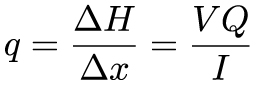
(You may notice that I got rid of the subscripts that are show in the above equation. That is because in the above equation, the coordinate system was specified: x was the long axis of the beam, y was along the thickness, and z was along the width. The above equation is general, it will be up to you to determine what the coordinates are, and therefore what the subscripts and relevant moments of area you need to solve for are.)
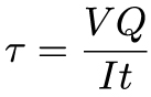
This equation for q has the units of [N m-1]. Force per length… just from dimensional analysis, we can observe that this shear force per unit length will be a stress if we divide q by a length scale. The relevant length scale in this case is the thickness of area of interest, t.
Now, from our bending lesson section on moments of area, we know how to calculate Q and I. Before we worry about specifics, there are a few things we can learn from this equation right away. Let's start by what we know: we can determine V from our shear and moment diagrams. We can calculate I based on the shape of the entire structure, and we can determine t from the width of our area of interest, i.e. over what width is this shear occurring. Determining Q is often the most challenging part of these types of problems – this is something that requires a lot of practice.
These equations for the transverse shear stress can be simplified for common engineering shapes. For instance, if you have a narrow rectangular beam, the equation simplifies to:
Where, c is half the beam's thickness, or in general c is the distance from the neutral axis to the outer surface of the beam. This equation is illustrative for a couple of reasons: first, the shear stress will be at a maximum value at the center of the beam, i.e. when y=0, and will be zero at the top and bottom of the beam. This is true for beams of more complex shape – there is zero transverse shear at the top and bottom. The next equation is valid for determine the maximum transverse shear stress in American standard (S-beam) or wide-flange (W-beam) beams.
Summary
Bending can induce both a normal stress and a transverse shear stress. The existence of this shear stress can be seen as cards slide past each other slightly when you bend a deck of cards. The magnitude of the shear stress becomes important when designing beams in bending that are thick or short – beams can and will fail in shear while bending. To calculate the transverse shear stress we use the applied shear force (which can be obtained from a shear-moment diagram), the first moment of area and thickness of the region of interest, and the second moment of area of the entire structure. The difficulty with these problems typically emerges while deciding what the region of interest is in a particular problem, and properly calculating Q for this region.
 This material is based upon work supported by the National Science Foundation under Grant No. 1454153. Any opinions, findings, and conclusions or recommendations expressed in this material are those of the author(s) and do not necessarily reflect the views of the National Science Foundation.