
Mechanics of Materials: Bending – Normal Stress
Moments of Area
In order to calculate stress (and therefore, strain) caused by bending, we need to understand where the neutral axis of the beam is, and how to calculate the second moment of area for a given cross section.
Let's start by imagining an arbitrary cross section – something not circular, not rectangular, etc.
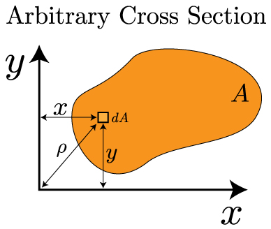
In the above image, the arbitrary shape has an area denoted by A. We can look at a small, differential area dA that exists some distance x and y from the origin. We can look at the first moment of area in each direction from the following formulas:
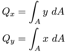
The first moment of area is the integral of a length over an area – that means it will have the units of length cubed [L3]. It is important because it helps us locate the centroid of an object. The centroid is defined as the "average x (or y) position of the area". Mathematically, this statement looks like this:
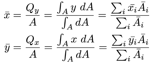
The far right side of the above equations will be very useful in this course – it allows us to break up a complex shape into simple shapes with known areas and known centroid locations. In most engineering structures there is at least one axis of symmetry – and this allows us to greatly simplify finding the centroid. The centroid has to be located on the axis of symmetry. For example:
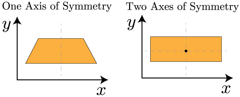
For the cross section on the left, we know the centroid has to lie on the axis of symmetry, so we only need to find the centroid along the y-axis. The cross section on the right is even easier – since the centroid has to line on the axes of symmetry, it has to be at the center of the object.
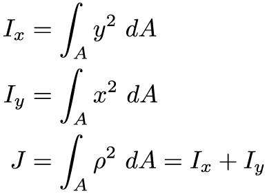
Now that we know how to locate the centroid, we can turn our attention to the second moment of area. As you might recall from the previous section on torsion, this is defined as:
And, finally sometimes we will need to determine the second moment of area about an arbitrary x or y axis – one that does not correspond to the centroid. In this case, we can utilize the parallel axis theorem to calculate it. In this case, we utilize the second moment of area with respect to the centroid, plus a term that includes the distances between the two axes.
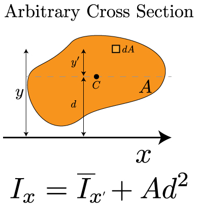
This equation is referred to as the Parallel Axis Theorem. It will be very useful throughout this course. As described in the introductory video to this section, it can be straightforward to calculate the second moment of area for a simple shape. For more complex shapes, we'll need to calculate I by calculating the individual I's for each simple shape and combining them together using the parallel axis theorem.
Shear and Moment Diagrams
Transverse loading refers to forces that are perpendicular to a structure's long axis. These transverse loads will cause a bending moment M that induces a normal stress, and a shear force V that induces a shear stress. These forces can and will vary along the length of the beam, and we will use shear & moment diagrams (V-M Diagram) to extract the most relevant values. Constructing these diagrams should be familiar to you from statics, but we will review them here. There are two important considerations when examining a transversely loaded beam:
- How is the beam loaded?
- point load, distributed load (uniform or varying), a combination of loads…
- How is the beam supported?
- simply supported, cantilevered, overhanging, statically indeterminate…
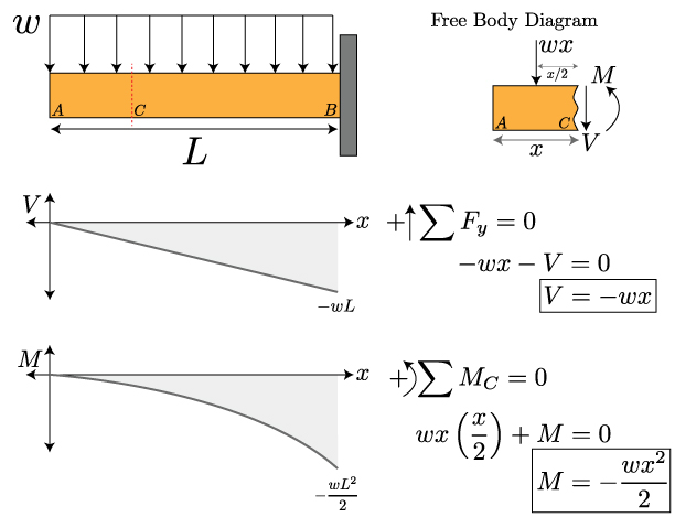
Knowing about the loads and supports will enable you to sketch a qualitative V-M diagram, and then a statics analysis of the free body will help you determine the quantitative description of the curves. Let's start by recalling our sign conventions.
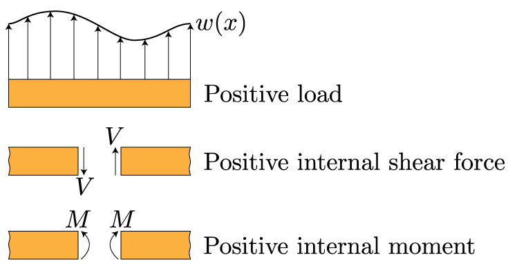
These sign conventions should be familiar. If the shear causes a counterclockwise rotation, it is positive. If the moment bends the beam in a manner that makes the beam bend into a "smile" or a U-shape, it is positive. The best way to recall these diagrams is to work through an example. Begin with this cantilevered beam – from here you can progress through more complicated loadings.
Normal Stress in Bending
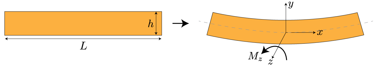
In many ways, bending and torsion are pretty similar. Bending results from a couple, or a bending moment M, that is applied. Just like torsion, in pure bending there is an axis within the material where the stress and strain are zero. This is referred to as the neutral axis. And, just like torsion, the stress is no longer uniform over the cross section of the structure – it varies. Let's start by looking at how a moment about the z-axis bends a structure. In this case, we won't limit ourselves to circular cross sections – in the figure below, we'll consider a prismatic cross section.
Before we delve into the mathematics behind bending, let's try to get a feel for it conceptually. Maybe the be way to see what's happening is to overlay the bent beam on top of the original, straight beam.
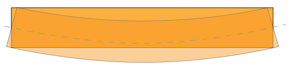
What you can notice now is that the bottom surface of the beam got longer in length, while the to surface of the beam got shorter in length. Also, along the center of the beam, the length didn't change at all – corresponding to the neutral axis. To restate this is the language of this class, we can say that the bottom surface is under tension, while the top surface is under compression. Something that is a little more subtle, but can still be observed from the above overlaid image, is that the displacement of the beam varies linearly from the top to the bottom – passing through zero at the neutral axis. Remember, this is exactly what we saw with torsion as well – the stress varied linearly from the center to the center. We can look at this stress distribution through the beam's cross section a bit more explicitly:
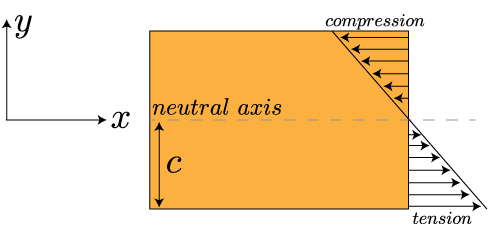
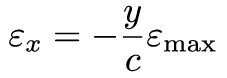
Now we can look for a mathematical relation between the applied moment and the stress within the beam. We already mentioned that beam deforms linearly from one edge to the other – this means the strain in the x-direction increases linearly with the distance along the y-axis (or, along the thickness of the beam). So, the strain will be at a maximum in tension at y = -c (since y=0 is at the neutral axis, in this case, the center of the beam), and will be at a maximum in compression at y=c. We can write that out mathematically like this:
Now, this tells us something about the strain, what can we say about the maximum values of the stress? Well, let's start by multiplying both sides of the equation by E, Young's elastic modulus. Now our equation looks like:
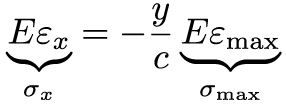
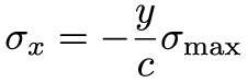
Using Hooke's law, we can relate those quantities with braces under them to the stress in the x-direction and the maximum stress. Which gives us this equation for the stress in the x-direction:
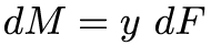
Our final step in this process is to understand how the bending moment relates to the stress. To do that, we recall that a moment is a force times a distance. If we can imagine only looking at a very small element within the beam, a differential element, then we can write that out mathematically as:
Since we have differentials in our equation, we can determine the moment M acting over the cross sectional area of the beam by integrating both sides of the equation. And, if we recall our definition of stress as being force per area, we can write:
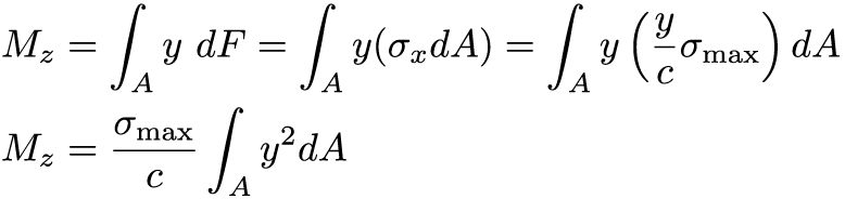
The final term in the last equation – the integral over y squared – represents the second moment of area about the z-axis (because of how we have defined our coordinates). In Cartesian coordinates, this second moment of area is denoted by I (in cylindrical coordinates, remember, it was denoted by J). Now we can finally write out our equation for the maximum stress, and therefore the stress at any point along the y-axis, as:
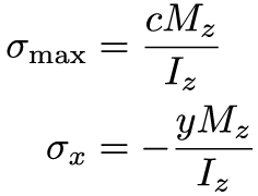
It's important to note that the subscripts in this equation and direction along the cross section (here, it is measured along y) all will change depending on the nature of the problem, i.e. the direction of the moment – which axis is the beam bending about? We based our notation on the bent beam show in the first image of this lesson.
Remember at the beginning of the section when I mentioned that bending and torsion were actually quite similar? We actually see this very explicitly in the last equation. In both cases, the stress (normal for bending, and shear for torsion) is equal to a couple/moment (M for bending, and T for torsion) times the location along the cross section, because the stress isn't uniform along the cross section (with Cartesian coordinates for bending, and cylindrical coordinates for torsion), all divided by the second moment of area of the cross section.
Summary
We learned about moments of area and shear-moment diagrams in this lesson. From the first moment of area of a cross section we can calculate the centroid. We learned how to calculate the second moment of area in Cartesian and polar coordinates, and we learned how the parallel axis theorem allows us to the second moment of area relative to an object's centroid – this is useful for splitting a complex cross section into multiple simple shapes and combining them together. We reexamined the concept of shear and moment diagrams from statics. These diagrams will be essential for determining the maximum shear force and bending moment along a complexly loaded beam, which in turn will be needed to calculate stresses and predict failure. Finally, we learned about normal stress from bending a beam. Both the stress and strain vary along the cross section of the beam, with one surface in tension and the other in compression. A plane running through the centroid forms the neutral axis – there is no stress or strain along the neutral axis. The stress is a function of the applied moment and second moment of area relative to the axis the moment is about.
 This material is based upon work supported by the National Science Foundation under Grant No. 1454153. Any opinions, findings, and conclusions or recommendations expressed in this material are those of the author(s) and do not necessarily reflect the views of the National Science Foundation.