
Mechanics of Materials: Beam Buckling
Critical Buckling Load
In the last lesson we learned about the equation of the elastic curve, and we described the deflection of a beam in response to transverse loading. In our first lesson about stress, we talked about axially loads that generate tensile and compressive stresses within a material, and in learning about strain we described how a structure will be compressed to a shorter length under an axial, compressive stress. We know from our own experiences that this isn't the only thing that can happen. Imagine pushing on a straw – is you push gently, nothing really happens, but once you push it with enough force, it will bow outward at the center. This phenomenon is known as buckling, and it is a very different structural response than in-plane compression. When designing columns and beams, buckling could result in a catastrophic failure – imagine the buckling of a bridge's vertical supports. Sometimes, it desirable to design for structures to buckle, for example the steering in your car is designed to buckle under significant loads to prevent it from further injuring the driver in a crash.
Let's look at an illustration of a cantilevered beam (free on one end and clamped on the other. There is a point force acting in the x axis that causes the beam to deflect in the y direction. (Since we're assuming the beam is homogenous and isotropic, there is no preference for buckling up or down. If the beam has a circular cross section, it can buckle in out of plane in any direction.)
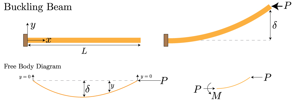
We can start analyzing this structure by writing down the differential equation for the elastic curve. From our free body diagram, we can replace the moment with the force times the change in out of plane deflection.
Let's define a new variable, k, to help simplify our following calculations:
We cannot now rewrite our elastic curve equations with our new variable.
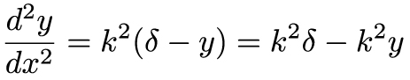
Next, we'll collect the the terms containing y on the same side of the equation.
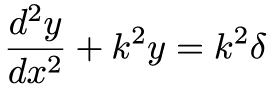
The above equation is a second-order, linear ordinary differential equation (ODE) known as the equation of free oscillations. It's general solution for position values of k2 (which, of course is the case for our definition of k) is given with two unknown constants, A & B.

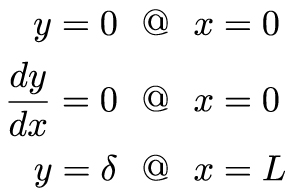
So, now we have a solution for y, but we need to determine what the value of the two unknowns. This is a boundary value problem, and for this we will use the boundary conditions on the beam. The beam is clamped at x=0, which means that the beam can't move up or down in the y direction at that point, i.e. y=0 at the clamped edge. Additionally, the clamped boundary requires the beam to be orthogonal to the wall, mathematically that means it must have zero slope at x=0, and the slope is the change in y over the change in x. There's a third condition that we'll need to use in a moment, and that is that the y position at the free edge of the beam, i.e. x=L, is equal to the deflection delta.
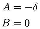
Using these boundary conditions, solving for A and B is straightforward. Let's start with the first boundary condition, putting in x=0 to our equation kills the second term (since the sin(x)=0) and requires that in order for y=0, A = – delta. The second boundary condition, differentiating y with respect to x, turns the first term into a sin(x) (and, as before, it goes away), it kills the last term (since delta isn't a function of x), and it turns the second term into a cos(0)=1. The only way for y=0 is for B=0.
So, putting our constants back into our general solution, we're left with the following equation:
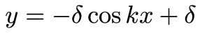
Here's where our third boundary condition enters. We're interested in solving this equation for k, since that will give us information about the load, P. Using our third boundary condition, which states that at x=L, y=delta, we reduce the above equation to the following:
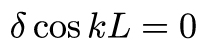
What we're left with can only be zero if delta=0 or the cos(kL)=0. The first case is a trivial case, it corresponds to no deflection, and therefore no buckling – it describes the case when the axially applied load simply compresses the beam in the x direction. For beam buckling, we're interested in the second case, i.e. cos(kL)=0. Cosine is a periodic function, and we know that cos(x)=0 at intervals of pi/2, 3pi/2, etc… And so, the above equation will equal zero when kL is equal to the following (where n is an integer ranging from 1 to infinity):
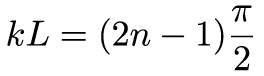
We can now replace k with the relevant variables of our problem, and we'll use n=1, since it will require the least bending of the beam, and therefore be the most energetically favorable solution:
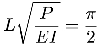
And finally, we can rearrange the above equation to solve for P, which will be a critical load that describes the onset of buckling for a beam with a free end and a clamped end.

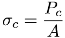
If, instead of the load we're interested in the stress, we will divide this load by the cross sectional area of the beam.
For two common cross sections, circular rods and rectangular beams, the critical stress takes the following forms:

Summary
In this lesson, we learned that above a critical load a beam under axial compressive will buckle out of plane. This critical load is dictated by the material properties and geometry of the structure. We can write it in a general form in terms of an effective length, Le, that enables us to consider a variety of boundary conditions.
 This material is based upon work supported by the National Science Foundation under Grant No. 1454153. Any opinions, findings, and conclusions or recommendations expressed in this material are those of the author(s) and do not necessarily reflect the views of the National Science Foundation.