Flow physics of an acoustic igniter
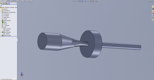
Rocket engines require an ignition source, or igniter, to initiate combustion. A variety of igniters are available for this use, such as hypergolic, pyrophoric, spark torch and catalytic. Most of these are viewed as high cost and operationally complex. Acoustic igniters offer an alternative. The acoustic igniter relies on the interaction between a supersonic jet flow issuing from a nozzle and a resonance tube placed closely downstream to produce a dramatic increase in temperature in the resonance tube. The igniter also includes an enclosure surrounding the gap between the nozzle and resonator. This system eliminates the need for electrical energy to drive spark systems to initiate combustion in liquid-propellant rockets, therefore reducing complexity, cost and weight. While the acoustic igniter concept has been in existence for years, only recently have commercial attempts been made to design and manufacture them for use in space propulsion. Most research in acoustic igniters has been experimental. In this project we are exploring whether computational techniques can be used to predict the behavior in an acoustic igniter.
Simulating the Physics
The acoustic igniter systems have been shown to have two main operating modes: regurgitant and screech. The operational mode is dependent upon the jet’s first shock cell length and the position of the resonator. Shock cells are best described in terms of a free jet. The simulations are performed using Overflow 2.1, a 3-D unsteady, compressible, finite-difference CFD code developed by NASA. The CFD predictions of the shock location and motion are highly dependent upon grid resolution and accuracy of the shear layer behavior. The shock is inherently unsteady. Therefore the location of the Mach disc and shock cell length are functions of time.

Figure 3: Top: Description of supersonic jet flow from a converging nozzle. Bottom: Associated nondimensional total pressure along the jet axis at a given instant.
The igniter behaves in either the regurgitant or screech mode depending on where the shock cell is interrupted due to the existence of the resonance tube. If the first shock cell is interrupted in the stable portion of the shock cell then the regurgitant mode is achieved. In this mode, temperature oscillations in the resonance tube occur on a time scale related to the axial extent of the tube. If the first shock cell is interrupted in its unstable region, the screech mode occurs. In this mode, intense heating at the end of the resonance tube is achieved and the oscillations in the tube are at very high frequency corresponding to the shock oscillation.
The CFD simulation has faithfully reproduced free jet flow. It is left to be shown that one can accurately reproduce the different modes and the resonator temperature for different igniter geometries and forcing pressures.
Related Publications:
“CFD Simulation of an Acoustic Igniter,” Keithe Baggett, Master’s Thesis, Boston University, May 2009.


